Table of Contents
- Key Takeaways
- Understanding the J-Type Anchor Bolt: Design, Function, and Mechanical Grip
- Why J-Type Anchor Bolts are Essential for Structural Integrity
- J-Type vs. L-Type Anchor Bolts: Identifying the Superior Choice for Your Project
- Primary Applications: From Industrial Machinery to Infrastructure
- Technical Specifications and Material Standards: The CTEG Quality Benchmark
- Evaluating Foundation Requirements: A Technical Selection Framework
- Installation Best Practices and Common Pitfalls to Avoid
- Frequently Asked Questions (FAQ) About J-Type Anchor Bolts
- Conclusion: Securing the Future of Construction with CTEG Solutions
Key Takeaways
- Mechanical Superiority: The unique hooked design of J-type anchor bolts provides exceptional pull-out resistance, making them superior for heavy-duty applications compared to straight anchors.
- Critical Selection: Choosing between J-type and L-type bolts depends heavily on load requirements and embedment depth; J-bolts generally offer higher stability in high-stress environments.
- Material Standards: CTEG manufactures J-bolts ranging from Grade 4.6 to High-Tensile 10.9, strictly adhering to ASTM, DIN, and JIS standards for global compliance.
- Installation Precision: Proper placement and alignment using templates are crucial to prevent structural misalignment and ensure long-term foundation integrity.
- Versatile Application: Essential for securing structural steel columns, heavy industrial machinery, and renewable energy infrastructure like wind turbines.
Understanding the J-Type Anchor Bolt: Design, Function, and Mechanical Grip
In the realm of heavy construction and structural engineering, the integrity of a building is defined not just by the steel beams that rise into the sky, but by the hidden fasteners that tether them to the earth. The J-type anchor bolt stands as a fundamental component in this equation. Yet, many project managers and procurement officers underestimate the complexity behind this seemingly simple fastener. A foundation failure is rarely a sudden event; it is often the cumulative result of minor oversights in bolt selection—specifically, failing to understand the mechanical grip required for specific load scenarios.
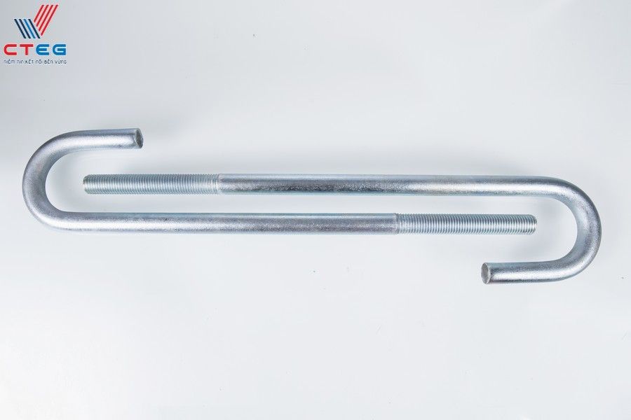
A J-type anchor bolt is a specialized fastener embedded into concrete foundations, characterized by its distinct “J” shape. Unlike post-installed anchors that rely on friction or chemical bonds, the J-bolt is a cast-in-place solution. Its design is engineered to solve a specific problem: slippage under tension. When a structure is subjected to uplift forces—whether from wind, seismic activity, or the vibration of heavy machinery—a straight bolt would simply slide out of the concrete matrix. The J-bolt, however, utilizes its geometry to lock into the cured concrete, transforming the foundation itself into a counterweight against these forces.
At CTEG, we recognize that the J-bolt is not merely a piece of steel; it is the primary interface between the static foundation and the dynamic structure above. Understanding its design is the first step in preventing catastrophic structural detachment.
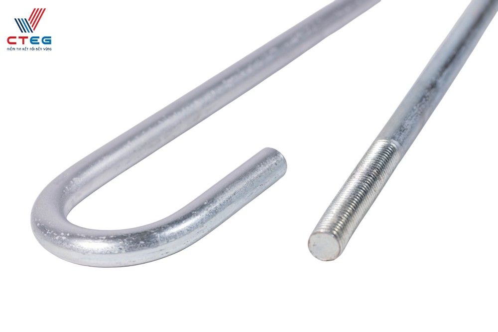
The Anatomy of a J-Bolt: Why the Hooked End Matters
The efficacy of a J-type anchor bolt lies entirely in its anatomy. While the threaded upper portion is visible and responsible for securing the base plate with nuts and washers, the “business end” of the bolt is buried deep within the concrete. The hook—typically bent at 180 degrees or a specific angle depending on the standard (such as ASTM F1554)—acts as a mechanical anchor.
This hook is not an arbitrary bend. It is a calculated geometric feature designed to distribute stress. When tensile load is applied to the exposed threads, the force travels down the shank and is transferred to the concrete via the hook. This transfer mechanism changes the nature of the resistance from simple friction (which can fail under vibration) to a bearing load against the concrete mass itself. For engineers, this means the bolt’s capacity is limited not just by the steel’s tensile strength, but by the concrete’s cone breakout strength. The hook effectively expands the “cone” of concrete that must be displaced for the bolt to fail, significantly increasing the load required to pull it out.
How J-Type Bolts Create Permanent Bonds in Wet Concrete
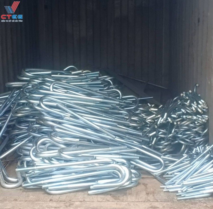
The installation process of J-type bolts is a race against time and chemistry. These bolts are “cast-in-place,” meaning they are positioned before the wet concrete is poured. As the concrete cures around the steel shank and the hooked end, it shrinks slightly and hardens, creating a permanent, monolithic bond. This is fundamentally different from mechanical expansion anchors, which induce stress on the surrounding concrete to maintain grip.
Because the J-bolt is enveloped by the aggregate and cement paste while the mix is fluid, there are no gaps or voids around the hook (assuming proper vibration during the pour). Once the concrete reaches its design strength, the J-bolt becomes an integral part of the foundation. Any attempt to withdraw the bolt would require crushing the concrete directly above the hook. This interaction ensures that the connection remains rigid even under cyclic loading, such as the operation of a large generator or the swaying of a steel tower. For projects requiring absolute permanence, the cast-in-place J-bolt is the industry standard for creating an unbreakable bond between steel and stone.
Why J-Type Anchor Bolts are Essential for Structural Integrity
Structural integrity is often compromised by the weakest link in the load path. In many industrial and commercial projects, that weak link is the connection point between the superstructure and the foundation. The problem is acute: dynamic forces are relentless. Wind loads on a pre-engineered steel building or the rhythmic vibrations of a manufacturing plant’s conveyor system constantly work to loosen connections. If the anchor bolts rely solely on friction or chemical adhesion, they are prone to “creep”—a slow, imperceptible movement that eventually leads to failure.
J-type anchor bolts are essential because they agitate this risk of failure by providing a mechanical interlock that is virtually immune to creep. They are the preferred choice for engineers who cannot afford to gamble with stability. By anchoring deep into the foundation, they ensure that the column base plates remain flush against the concrete, transmitting loads effectively and preventing the “rocking” motion that can fatigue steel members. Without the secure embedment provided by J-bolts, structures are significantly more vulnerable to overturning moments and shear forces. In essence, the J-bolt is the insurance policy for the entire structural frame.
Superior Pull-Out Resistance for High-Stress Environments
Pull-out resistance is the defining metric for anchor bolt performance. In high-stress environments—such as coastal areas prone to hurricanes or industrial zones with heavy crane operations—the uplift forces can be immense. A straight bolt has very little resistance to these vertical forces; it relies entirely on the bond stress between the steel surface and the concrete.
The J-type bolt, conversely, engages the concrete’s compressive strength. To pull a J-bolt out, the force must be sufficient to shear through the concrete caught within the hook. This creates a resistance value that is exponentially higher than a straight rod of the same diameter. For example, in a high-tension application like a transmission tower, the J-bolt ensures that the tension is dissipated deep into the foundation block, preventing the bolt from yielding or slipping. This superior resistance is why J-bolts are non-negotiable in specifications for heavy structural steel and dynamic equipment mounting.
Ensuring Long-Term Stability Against Vibrations and Wind Loads
Vibration is the silent killer of threaded connections. In factories housing stamping presses or turbines, the constant oscillation can cause standard mechanical anchors to loosen over time. Similarly, wind loads create a cyclic push-pull effect on building columns. This repetitive stress cycle can degrade the interface between the bolt and the concrete.
J-type anchor bolts mitigate this risk through their geometry. The hook acts as a dampener of sorts, anchoring the bolt so securely that it moves in unison with the foundation rather than vibrating independently within the hole. This prevents the micro-cracking of concrete around the bolt shank that often leads to failure in other anchor types. Furthermore, when combined with proper grouting and tensioning, J-bolts maintain their preload indefinitely. For facility managers, this translates to reduced maintenance costs and, more importantly, the assurance that the facility remains safe and operational regardless of the environmental or operational loads applied to it.
J-Type vs. L-Type Anchor Bolts: Identifying the Superior Choice for Your Project
One of the most common dilemmas facing procurement managers and site engineers is the choice between J-type and L-type anchor bolts. On the surface, they appear similar—both are bent, cast-in-place anchors. However, treating them as interchangeable is a critical error that can compromise a project’s structural certification. The confusion often leads to the wrong specification, resulting in either over-engineering (wasting budget) or under-engineering (risking safety).
The primary difference lies in the geometry of the bend and how it interacts with the concrete. While L-bolts (90-degree bend) are excellent for many standard applications, J-bolts typically offer a more aggressive mechanical interlock due to the geometry of the hook, which can be 180 degrees or a tight J-curve. This section aims to solve the selection paralysis by clearly delineating where the J-shape is the superior engineering choice.
| Feature | J-Type Anchor Bolt | L-Type Anchor Bolt |
|---|---|---|
| Shape | Hooked end (often 180° or tight curve) | 90° right-angle bend |
| Pull-Out Resistance | Superior: Hook engages more concrete mass. | Standard: Relies on the bearing area of the L-leg. |
| Primary Use Case | Heavy tension loads, dynamic machinery, tall structures. | Light poles, sign posts, standard building columns. |
| Installation Complexity | Moderate: Requires careful threading through rebar cages. | Low: Easier to position in dense rebar. |
Structural Scenarios Where the J-Shape Outperforms the L-Shape
The J-shape is not just an aesthetic variation; it is a functional upgrade for specific structural scenarios. The J-bolt outperforms the L-bolt primarily in situations where tensile loads are dominant and variable. For instance, in the construction of a cantilevered canopy or a high-mast lighting tower, the uplift forces at the base are significant. An L-bolt, while strong, has a shorter “leg” to bear against the concrete. Under extreme tension, the concrete above the L-leg can shear, leading to failure.
The J-bolt, particularly those with a 180-degree hook, creates a deeper and more complex stress cone. This makes it the superior choice for:
- Seismic Zones: Where ground motion creates unpredictable vertical accelerations.
- Suspended Equipment: Where gravity loads are reversed.
- Heavy Industrial Machinery: Where the bolt must resist the machine trying to “jump” off the foundation.
In these scenarios, the J-shape provides a safety factor that the L-shape cannot match without significantly increasing the bolt diameter or embedment depth.
Comparing Load Capacities and Embedment Depth Requirements
When calculating load capacities, engineers look at the “development length” of the bolt. Generally, J-bolts can achieve higher pull-out values with slightly less horizontal space requirement compared to L-bolts, although they may require careful vertical placement. The hook of the J-bolt allows it to develop full tensile strength with a specific embedment depth that might be more efficient in deep, narrow footings.
Conversely, L-bolts require a sufficient horizontal leg length to generate holding power. If the foundation is congested with rebar, finding space for a long L-leg can be problematic. A J-bolt, with its compact hook, can often be maneuvered into tighter reinforcement cages while still delivering the required holding power. However, it is crucial to note that the specific load capacity is always a function of the bolt diameter, steel grade, and concrete strength (psi/MPa). At CTEG, we advise clients to review the specific pull-out charts for our Grade 8.8 and 10.9 bolts to make an informed decision based on the exact kN (kilonewton) requirements of their project.
Primary Applications: From Industrial Machinery to Infrastructure
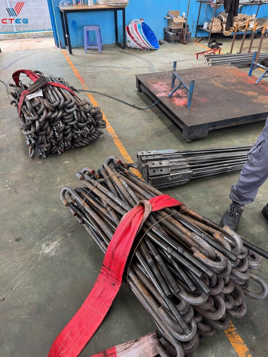
The versatility of J-type anchor bolts allows them to serve as the backbone for a wide array of construction sectors. From the sprawling industrial parks of Binh Duong to the renewable energy fields of the Central Highlands, these fasteners are ubiquitous. However, their application is not generic; each use case demands specific configurations of diameter, length, and material grade.
At CTEG, we supply J-bolts for projects ranging from pre-engineered steel buildings to complex infrastructure like the Long Thanh International Airport. The common thread in all these applications is the need for a connection that can withstand both static dead loads and dynamic live loads. Whether it is anchoring a 50-ton press or a 100-meter wind turbine tower, the J-bolt provides the necessary assurance that the structure will remain grounded.
Securing Structural Steel Columns and Heavy Equipment
In the construction of factories and warehouses, the connection between the steel column and the concrete plinth is critical. J-type anchor bolts are the standard solution here. They are typically arranged in a pattern (often 4, 6, or 8 bolts) to secure the base plate. This arrangement resists the “moment” or bending force applied to the column by wind or crane loads. For heavy equipment, such as stamping machines, compressors, or turbines, the role of the J-bolt shifts to vibration control. The bolts must be tightened to a specific torque to create a clamping force that prevents the machine from shifting. The hooked end ensures that even under intense vibration, the bolt does not loosen from the concrete, maintaining the machine’s alignment and preventing costly downtime.
Supporting Renewable Energy: Wind Turbines and Solar Arrays
The renewable energy sector presents some of the most demanding environments for anchor bolts. Wind turbines, in particular, generate massive overturning moments. The foundation bolts must resist the tower’s tendency to tip over in high winds. High-tensile J-type bolts (often Grade 8.8 or 10.9) are frequently used in the foundation cages of these towers to anchor the base ring. Similarly, in large-scale solar farms, the racking systems are subjected to wind uplift. J-bolts provide the necessary anchorage to keep the solar arrays secure during storms. CTEG has been a proud supplier for numerous wind and solar projects, providing hot-dip galvanized J-bolts that resist corrosion in these often exposed and harsh environments.
Technical Specifications and Material Standards: The CTEG Quality Benchmark
In the fastener industry, “quality” is not a buzzword; it is a measurable adherence to international standards. A J-bolt that fails to meet its specified tensile strength can lead to catastrophic structural failure. Therefore, sourcing from a manufacturer that strictly follows ASTM, DIN, and JIS standards is non-negotiable. CTEG positions itself as a technical authority, ensuring that every batch of bolts we produce—from M12 to M64—is rigorously tested and certified.
We do not just sell steel; we sell certified strength. Our manufacturing process utilizes advanced ERP management to track every lot, ensuring full traceability from the raw material billet to the finished, threaded bolt. This level of transparency is essential for projects requiring CO/CQ (Certificate of Origin/Certificate of Quality) documentation.
Understanding Strength Grades: From 4.6 to High-Tensile 10.9
The “grade” of a bolt dictates its mechanical properties, specifically its tensile strength and yield strength. Choosing the wrong grade is a common engineering pitfall.
- Grade 4.6 & 5.6 (Mild Steel): These are standard grades used for light to medium applications, such as securing light poles or small steel structures. They offer good ductility but lower tensile strength.
- Grade 6.6 & 8.8 (Medium to High Strength): Grade 8.8 is the workhorse of the structural steel industry. It offers a high tensile strength (minimum 800 MPa), making it suitable for main structural columns and heavy machinery.
- Grade 10.9 (High Tensile): Reserved for the most critical applications, such as wind turbine foundations or heavy bridges. These bolts are heat-treated to achieve exceptional strength (minimum 1000 MPa) but require careful handling to avoid hydrogen embrittlement during plating.
CTEG supplies all these grades, ensuring that engineers can match the bolt’s capacity exactly to the calculated loads of their specific project.
Surface Treatments: Hot-Dip Galvanizing vs. Electro-Zinc Plating
Steel rusts. In a foundation, corrosion can be disastrous, expanding the metal and cracking the concrete. Therefore, the surface treatment of a J-bolt is as important as its steel grade.
- Black (Plain Finish): Suitable only for bolts that will be completely encased in concrete and not exposed to moisture.
- Electro-Zinc Plating (Xi trắng/Xi vàng): Provides a thin layer of protection, suitable for indoor environments or temporary structures.
- Hot-Dip Galvanizing (Mạ kẽm nhúng nóng): The gold standard for outdoor and industrial durability. The bolt is dipped in molten zinc, creating a thick, metallurgical bond that protects against corrosion for decades. CTEG specializes in hot-dip galvanizing, ensuring threads remain functional even after the coating process.
Evaluating Foundation Requirements: A Technical Selection Framework
Selecting the right J-bolt is not a guessing game; it is a calculated engineering decision. To assist our clients, CTEG advocates for a technical selection framework that moves beyond simple catalog browsing. This framework requires engineers and procurement teams to evaluate the foundation requirements holistically.
“The most expensive bolt is the one that fails. The second most expensive is the one that is over-specified. True engineering value lies in calculating the exact diameter and length required for the load, and not a millimeter more.”
– CTEG Technical Engineering Team
This section provides a guide to the variables that must be calculated to ensure the selected J-bolt meets the project’s safety and durability requirements.
Calculating Diameter and Length Based on Project Loadings
The diameter of the bolt (e.g., M24, M36) is directly correlated to its tensile and shear capacity. Engineers must calculate the total uplift and shear forces acting on the column base and divide this by the number of bolts to determine the required diameter. However, length is equally critical. The total length of a J-bolt includes:
- Embedment Depth: The portion buried in concrete, which determines pull-out resistance.
- Projection: The portion sticking out of the concrete to accommodate the grout layer, base plate, washer, nut, and stick-out.
A common error is underestimating the projection, leaving insufficient thread to secure the nut. CTEG advises a detailed review of base plate thickness and grout specifications before ordering to ensure the manufactured length is precise.
Compliance with International Standards: ASTM, DIN, and JIS
Global construction projects often specify different standards. A J-bolt for a Japanese-funded factory might require JIS B 1178 compliance, while an American design might call for ASTM F1554.
* ASTM F1554: The standard specification for anchor bolts, covering various grades (36, 55, 105) and shapes.
* DIN 529: A German standard specifically for masonry and foundation bolts.
* JIS B 1178: The Japanese Industrial Standard for foundation bolts.
CTEG’s manufacturing capabilities are flexible enough to produce bolts strictly adhering to any of these standards, ensuring that your project passes all technical audits and inspections.
Installation Best Practices and Common Pitfalls to Avoid
Even the highest-grade J-bolt will fail if installed incorrectly. The transition from the drawing board to the muddy reality of a construction site is where many errors occur. Misalignment is the most frequent issue; if the bolts are not perfectly vertical or if the spacing does not match the base plate holes, the steel column cannot be erected. This leads to costly on-site modifications like slotting base plates or, worse, cutting and chemically re-anchoring bolts.
To solve this, CTEG recommends a strict installation protocol. We have seen firsthand, through our involvement in major projects like the LEGO factory in Binh Duong, that adherence to a Standard Operating Procedure (SOP) is the only way to guarantee precision.
The On-Site SOP for Precise Bolt Placement
To ensure zero-error installation, follow this CTEG-recommended SOP:
- Template Usage: Never set bolts individually. Use a rigid steel or plywood template that matches the column base plate pattern exactly.
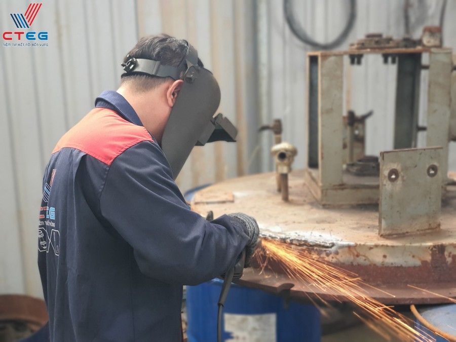
- Secure to Rebar: Rigidly fasten the J-bolts to the reinforcement cage using wire or welding (if permitted by the steel grade) to prevent movement during the concrete pour.
- Protect the Threads: Wrap the exposed threads with tape or use plastic caps. Concrete splatter on threads can make nut installation impossible later.
- Vibration Control: During the pour, ensure the vibrator does not hit the bolts directly, which can knock them out of alignment.
- Post-Pour Check: Immediately after pouring, while the concrete is still wet, re-verify the position and projection of the bolts against the datum lines.
Frequently Asked Questions (FAQ) About J-Type Anchor Bolts
What is the difference between J-bolts and L-bolts?
The main difference is the shape of the embedded end. J-bolts have a hook (often 180 degrees or a tight curve), while L-bolts have a 90-degree bend. J-bolts generally offer superior pull-out resistance due to the hook engaging more concrete mass, making them better suited for high-tension applications.
Can I weld J-type anchor bolts to the rebar cage?
It depends on the grade of steel. Low carbon steels (like Grade 36 or 4.6) are generally weldable. However, high-strength heat-treated bolts (like Grade 10.9) should never be welded, as the heat can alter the steel’s properties and cause embrittlement. Always consult the project engineer and CTEG’s technical specifications before welding.
What is the standard embedment depth for a J-bolt?
There is no single “standard” depth; it depends on the bolt diameter, the load requirements, and the concrete strength. However, a general rule of thumb often used in preliminary design is 12 to 15 times the bolt diameter. Precise depth must be calculated by a structural engineer.
Does CTEG provide certification for their J-bolts?
Yes. CTEG provides full documentation for all our products, including Mill Test Certificates (MTC), certificates of origin, and tensile strength test reports. We ensure compliance with ASTM, DIN, JIS, and TCVN standards.
How do I prevent J-bolts from rusting before the steel structure is installed?
If the bolts are not hot-dip galvanized, they should be painted or coated with a rust inhibitor immediately after installation. Keeping the threads wrapped or capped until the nuts are installed is also a critical best practice.
Conclusion: Securing the Future of Construction with CTEG Solutions
The J-type anchor bolt is more than a simple fastener; it is the foundational element that grants stability to our built environment. From the towering wind turbines of the Central Highlands to the massive industrial workshops driving Vietnam’s economy, the reliability of these bolts is paramount. Choosing the right bolt involves navigating a complex landscape of tensile strengths, material grades, and installation methodologies.
At Cường Thịnh (CTEG), we bridge the gap between technical complexity and practical application. With over a decade of experience and a portfolio that includes national landmarks like the Long Thanh Airport, we are committed to delivering not just products, but peace of mind. Whether you require the high-tensile strength of Grade 10.9 or the corrosion resistance of hot-dip galvanizing, CTEG is your trusted partner in building a secure future. Do not leave your foundation to chance—choose the expertise and quality that only a dedicated industry leader can provide.

Có thể bạn quan tâm
Những lưu ý quan trọng khi lựa chọn bu lông neo chữ L cho dự án
Real-World Applications of J-Type Anchor Bolts in Major Infrastructure: A Comprehensive Guide
The Engineering Backbone: How Anchor Bolts Secure Mega-Structures Like Long Thanh International Airport
Tại sao bu lông neo chữ L là lựa chọn hàng đầu cho móng công trình?