Table of Contents
- Introduction to J-Type Anchor Bolts in Modern Structural Foundations
- Decoding the J-Type Anchor Bolt Drawing: Key Symbols and Notations
- Technical Design Specifications: Materials, Grades, and Standards
- Translating Architectural Blueprints into Manufacturing Orders at CTEG
- Engineering Considerations: Embedment Length and Load-Bearing Capacity
- Best Practices for Installing J-Type Anchor Bolts in Concrete
- Frequently Asked Questions (FAQ)
- Conclusion: Ensuring Structural Integrity with Precision-Engineered J-Bolts
- Ultra-Specific Interpretation: Master the precise reading of J-bolt drawings, distinguishing critical dimensions like hook length, bend radius, and thread pitch to prevent costly on-site errors.
- Material Mastery: Understand the specific applications of material grades from 4.6 to 10.9 and international standards (ASTM F1554, DIN, JIS) that dictate structural integrity.
- Manufacturing Insight: Gain a unique behind-the-scenes look at how CTEG translates complex architectural blueprints into precision-manufactured orders for major projects like Long Thanh Airport.
- Urgent Safety Protocols: Learn the essential engineering considerations for embedment depth and pull-out resistance to ensure immediate and long-term foundation stability.
Introduction to J-Type Anchor Bolts in Modern Structural Foundations
In the high-stakes world of heavy construction, the integrity of a skyscraper, a wind turbine, or a massive industrial factory often rests on the smallest details buried within the concrete: the anchor bolts. Specifically, J-type anchor bolts serve as the critical interface between the concrete foundation and the structural steel columns above. However, a drawing is only as valuable as the engineer’s ability to interpret it and the manufacturer’s ability to execute it. Misreading a specification regarding hook geometry or steel grade is not merely a clerical error; it is an urgent structural risk that can lead to catastrophic failure or expensive project delays.
At Cường Thịnh (CTEG), we understand that precision is the bedrock of safety. As a leading provider of fastening solutions in Vietnam, supplying major projects from the LEGO Factory to renewable energy plants, we bridge the gap between theoretical design and physical reality. This guide goes beyond basic definitions to provide an ultra-specific, useful analysis of J-type anchor bolt drawings, ensuring that every specification—from the bend radius to the thread pitch—is understood, verified, and manufactured to the highest international standards.
Decoding the J-Type Anchor Bolt Drawing: Key Symbols and Notations

To the untrained eye, an anchor bolt drawing might appear to be a simple schematic of a bent rod. However, for structural engineers and procurement specialists, these drawings are dense with ultra-specific data that dictate the mechanical performance of the connection. Successfully decoding these symbols is the first step in ensuring that the “J” shape performs its intended function: resisting pull-out forces through mechanical interlock.
The drawing typically presents a profile view of the bolt, accompanied by a data table or “schedule” listing dimensions for various bolt marks (e.g., J1, J2). The most critical error often occurs in misidentifying the reference points for these dimensions. Is the length measured from the inside of the hook or the outside? Does the thread length include the run-out? Clarity here is useful and necessary to avoid ordering thousands of bolts that are technically “to spec” but functionally incompatible with the site conditions.
Furthermore, notations regarding tolerances are often overlooked. A standard drawing might specify a diameter of M24, but the tolerance class (e.g., 6g for threads) determines how well the nut will fit, especially after galvanizing. At CTEG, we emphasize that reading the drawing is not just about checking geometry; it is about understanding the functional relationship between the bolt, the concrete, and the steel plate it secures. The following sections break down the three most critical components of these drawings.
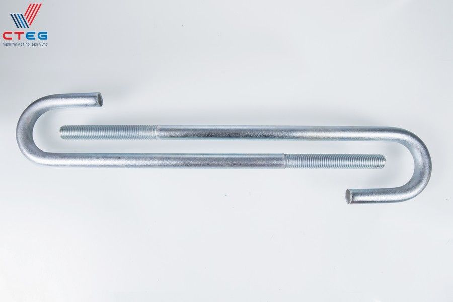
Understanding Hook Length (L) and Bend Radius Specifications
The defining feature of a J-bolt is its hook, but the “hook length” is a dimension that frequently causes confusion. On technical drawings, this is often denoted as dimension C or L2. It is crucial to verify whether the designer has specified this length from the inner surface of the bend or the outer edge. In structural engineering, the hook is responsible for creating the mechanical interlock with the concrete. If the hook is too short, it may fail to develop the necessary pull-out resistance, leading to concrete slippage.
Equally urgent is the specification of the bend radius. A bend that is too sharp can induce stress concentrations in the steel, leading to cracking during fabrication or under load. Conversely, a radius that is too large may not fit within the reinforcement cage of the foundation. Drawings should explicitly state the minimum bend radius, typically a multiple of the bolt diameter (e.g., 2d or 3d), to ensure the material’s structural integrity is maintained during the cold-bending process.
Identifying Thread Pitch and Thread Length in Technical Blueprints
Thread specifications are where precision is non-negotiable. A drawing callout of “M36” is insufficient without defining the thread pitch. While coarse thread (UNC or metric coarse) is standard for construction due to its durability and ease of assembly, certain high-precision applications may demand fine threads. Misidentifying the pitch will render the bolts incompatible with the nuts, halting installation instantly.
Additionally, thread length (often denoted as T) must be scrutinized. This dimension dictates how much adjustment is available for the leveling nuts and base plate. A common issue we see at CTEG is drawings that do not account for the “projection” required above the concrete. The thread length must be sufficient to accommodate the grout thickness, the base plate, washers, and the nut, with enough protrusion to ensure full thread engagement. If the thread length is underestimated on the drawing, the nut cannot be tightened, compromising the column’s stability.
Interpreting Dimensional Callouts for Diameter and Total Length
The most fundamental, yet frequently misinterpreted, dimensions are the nominal diameter and the total length. In J-bolt drawings, the diameter (e.g., M24, M48, M64) refers to the major diameter of the threaded section. However, the unthreaded shank diameter can vary depending on the manufacturing method (cut thread vs. rolled thread). For rolled threads, the shank diameter is slightly less than the nominal diameter, which is a critical detail for engineers calculating tensile strength.
Total length is equally specific. Is the length measured overall (from the top of the bolt to the bottom of the hook) or is it the “developed length” of the straight rod before bending? Standard practice usually dictates measuring from the top of the bolt to the bottom of the bend. Clarifying this definition is unique to each project and essential for accurate fabrication.
Technical Design Specifications: Materials, Grades, and Standards
Once the geometry is decoded, the focus shifts to the metallurgy. The “J” shape provides the mechanical hold, but the material grade determines the bolt’s ability to withstand tensile loads, shear forces, and environmental stressors. In the context of the 4U framework, this information is useful for selection and urgent for safety compliance. A bolt made of the wrong steel grade may look identical to the correct one but will fail catastrophically under design loads.
At CTEG, we supply a vast range of grades to meet diverse structural needs. The specification on the drawing—often a simple code like “Gr. 8.8” or “F1554-55″—dictates the entire manufacturing supply chain, from the raw steel billet selection to the heat treatment process. Engineers must specify these grades based on the calculated loads and the environmental conditions of the project site. For instance, a wind turbine foundation requires significantly higher tensile strength and fatigue resistance than a standard warehouse column. Ignoring these specifications or substituting materials without approval is a prohibited conduct that endangers lives.
Furthermore, the design specification must address the “condition” of the material. Is it weldable? Does it require impact testing for cold climates? These ultra-specific requirements are embedded in the standards referenced in the blueprints. Understanding the hierarchy of these standards ensures that the bolts delivered to the site are not just metal rods, but engineered components certified for performance.
Common Material Grades: From 4.6 to High-Strength 10.9 Solutions
Material grades are the shorthand for strength. The most common grade for general construction J-bolts is Grade 4.6 (or ASTM A307), offering moderate strength and excellent ductility, making it ideal for standard building foundations where high tension is not the primary concern. These bolts are cost-effective and easily bent without cracking.
However, for heavy industrial projects or structures subject to dynamic loads, such as the projects CTEG supplies for the energy sector, High-Strength Grades 8.8 and 10.9 are essential. Grade 8.8 offers nearly double the tensile strength of 4.6, allowing for smaller diameters to carry heavier loads. Grade 10.9 is reserved for the most critical applications requiring extreme strength. It is vital to note that high-strength bolts require careful handling during bending; improper heating or bending can destroy the heat treatment properties. CTEG’s capability to supply this full range, from M12 to M64, ensures we can match the exact grade requirement of any blueprint.
Adhering to International Standards: ASTM F1554, DIN, and JIS Compliance
Global construction projects demand global compliance. The gold standard for anchor bolts is ASTM F1554, a specification designed specifically for anchor bolts embedded in concrete. Unlike generic bolt standards, F1554 covers three grades (36, 55, and 105) and includes requirements for weldability and ductility, which are critical for J-bolts that must deform rather than snap under seismic stress.
In addition to ASTM, CTEG strictly adheres to DIN (German) and JIS (Japanese) standards, as well as Vietnam’s TCVN. For example, DIN standards often dictate precise dimensional tolerances that ensure compatibility with European machinery. Compliance is not optional; every batch leaving our factory is accompanied by CO/CQ (Certificate of Origin/Quality) and tensile test reports. This transparency builds trust, proving that the bolts meet the rigorous demands of international consultants and contractors.
Surface Treatments for Corrosion Resistance: Hot-Dip Galvanizing vs. Zinc Plating
The longevity of a foundation depends on the bolt’s resistance to rust. The drawing will specify the surface treatment, a detail that significantly impacts the bolt’s lifespan. Hot-Dip Galvanizing (HDG) is the superior choice for outdoor or harsh environments. It involves submerging the bolt in molten zinc, creating a thick, metallurgical bond that provides decades of protection. This is CTEG’s strength, ensuring durability for marine or industrial projects.
Alternatively, Zinc Plating (Electro-galvanizing) offers a thinner coating suitable for indoor, dry environments where aesthetics and precise thread fit are priorities. Black (Plain) finish is used when the bolt will be fully encased in concrete or painted later. Selecting the wrong finish—such as using black bolts in a coastal environment—is a recipe for rapid structural degradation. We ensure the galvanizing thickness meets standards like ASTM A153 to guarantee long-term performance.
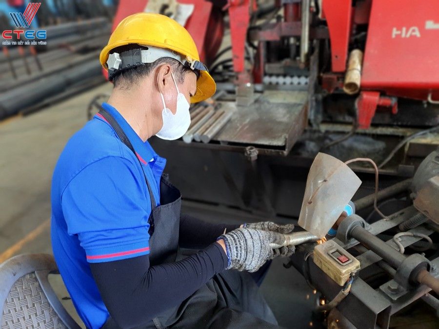
Translating Architectural Blueprints into Manufacturing Orders at CTEG
The transition from a digital PDF drawing to a physical steel bolt is where CTEG’s unique value proposition comes into play. This process is not automated; it requires human expertise to interpret, validate, and execute. For our clients, this means the difference between receiving a pallet of scrap metal and receiving precision-engineered components ready for installation.
At CTEG, we view the blueprint as a contract of performance. Our role goes beyond simple fabrication; we act as a technical partner. When we receive a drawing for a complex project—like the massive steel structures at the Long Thanh International Airport or the intricate foundations of the LEGO Factory—we initiate a rigorous translation process. We convert architectural intent into manufacturing reality, ensuring that “what you see” on the plan is exactly “what you get” on the site. This section details the specific activities and skills we apply to ensure every order is perfect.
The Critical Review Process for Custom J-Bolt Fabrication
Before a single rod is cut, CTEG’s technical team performs a comprehensive review of the customer’s drawings. This is a proactive “Skills” application where we identify potential conflicts or ambiguities. For instance, we check if the specified thread length allows for proper tensioning given the bolt’s diameter and grade. We verify that the bend radius specified is feasible for the chosen material grade without compromising its structural integrity.
If a drawing specifies a non-standard thread pitch or an impossible bend geometry for a high-strength grade (like bending Grade 10.9 without stress relief), our team immediately consults with the client. We propose optimizations that maintain structural safety while improving manufacturability and reducing costs. This consultative approach prevents the “blind manufacturing” that leads to site rejections. We use our ERP system to lock in these specifications, ensuring that the production floor follows the approved technical review down to the millimeter.
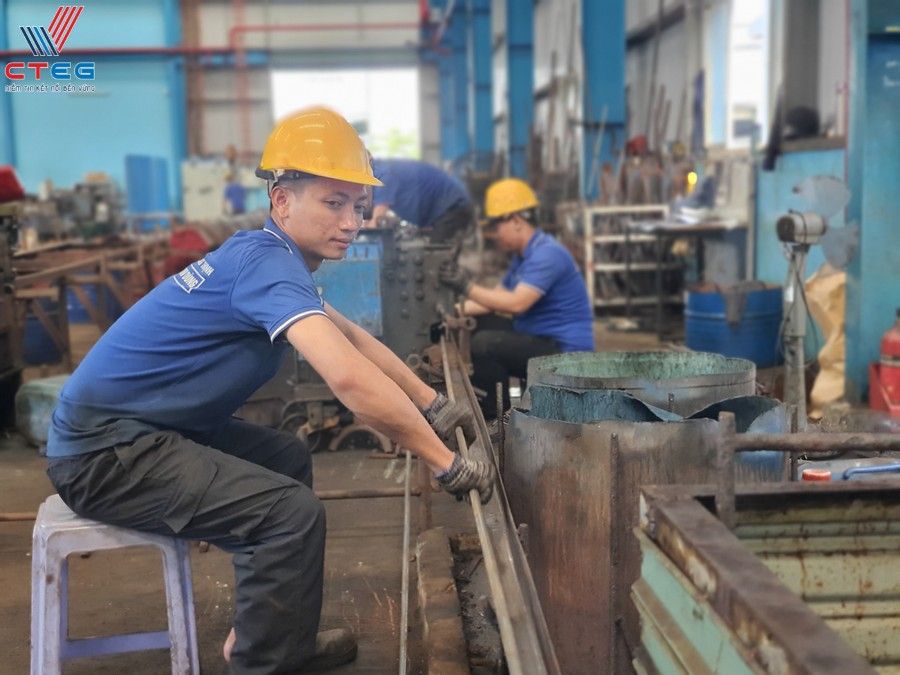
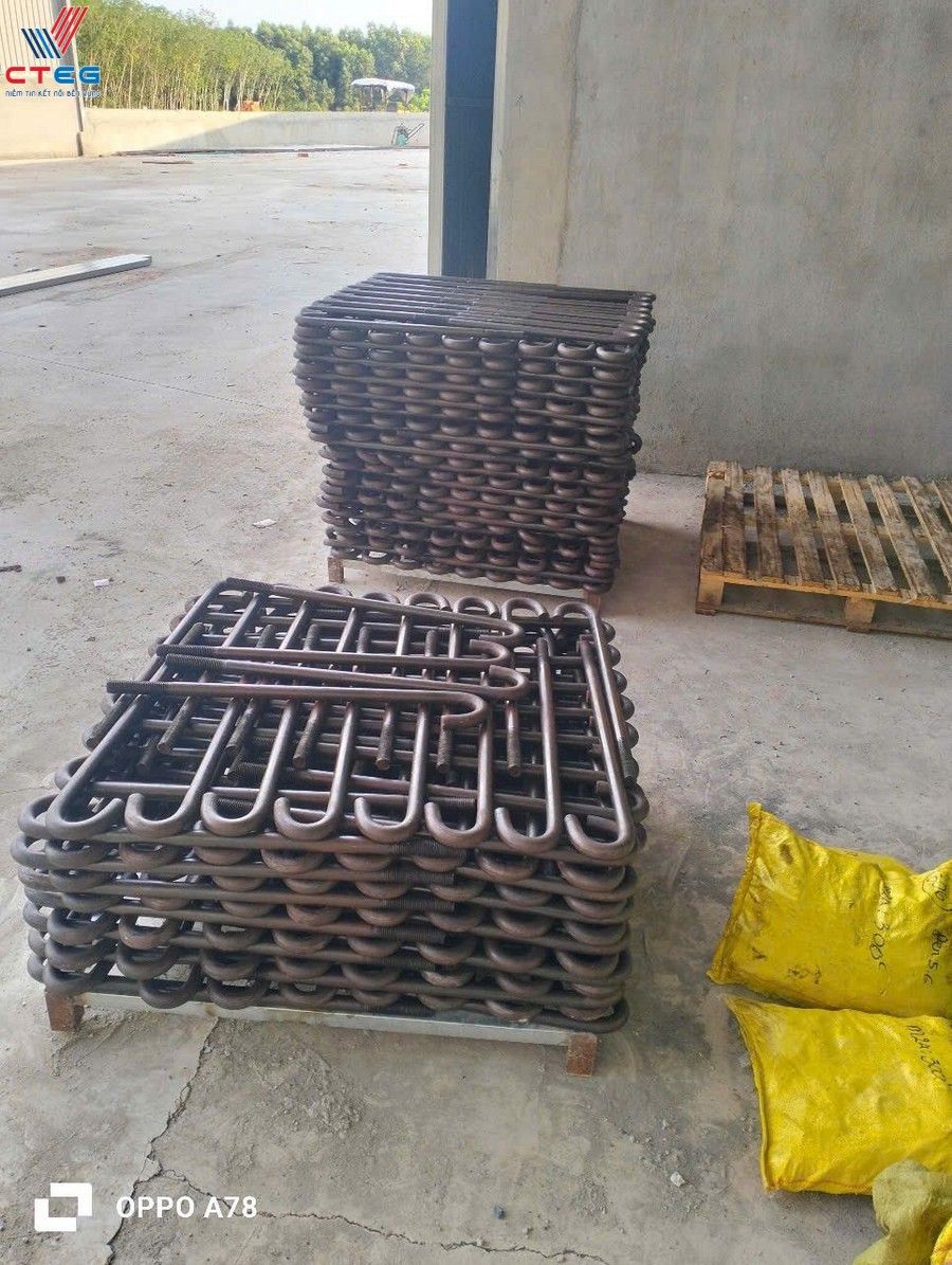
Ensuring Precision: How CTEG Validates Technical Specifications for Large-Scale Projects
For large-scale projects, consistency is key. When manufacturing thousands of J-bolts for a wind farm or a factory complex, a deviation of even 1mm can cause compounding errors during steel erection. CTEG employs a multi-stage validation process. First, raw materials are tested for chemical composition and mechanical properties to ensure they meet the grade requirements (e.g., confirming the yield strength of Grade 8.8 steel).
During fabrication, we utilize precision CNC machinery for threading and bending, ensuring uniformity across the entire batch. We conduct random sampling checks on dimensions—hook length, total length, and thread pitch—using calibrated gauges. For critical orders, we perform tensile testing on finished bolts to validate that the manufacturing process has not altered the material’s properties. This ultra-specific attention to detail is why partners like ATAD and Dai Dung trust CTEG. We provide the documentation—mill test reports and factory certifications—that proves every bolt meets the stringent requirements of the original blueprint.
Engineering Considerations: Embedment Length and Load-Bearing Capacity
Understanding the drawing is one thing; understanding the physics behind it is another. The design of a J-bolt is governed by its ability to transfer loads from the structure into the concrete foundation. This transfer relies heavily on two factors: the depth of embedment and the mechanical interlock provided by the hook. For engineers and contractors, grasping these concepts is urgent to prevent foundation uplift or breakout failure.
The “J” hook acts as an anchor. When an uplift force pulls on the bolt, the hook engages with the concrete, distributing the stress. If the bolt is too shallow, the concrete above the hook may shatter (breakout failure). If the bolt is deep enough but the steel is too weak, the bolt itself will snap (steel failure). Balancing these factors is the core of anchor bolt design. At CTEG, we ensure our bolts are manufactured to support these calculated loads, providing the necessary tensile strength to match the engineer’s embedment design.
Calculating Minimum Embedment Depth for Structural Stability
Embedment depth ($h_{ef}$) is the vertical distance from the surface of the concrete to the bearing point of the hook. This dimension is critical. A general rule of thumb often cited is an embedment of 12 to 20 times the bolt diameter, but modern design codes (like ACI 318) require more complex calculations based on concrete strength, bolt spacing, and edge distance.
The drawing must specify a minimum embedment that ensures the concrete cone failure load is higher than the steel’s tensile strength. In simple terms, you want the steel to stretch before the concrete cracks. If a drawing shows an embedment depth that seems insufficient for the bolt diameter (e.g., a short M36 bolt), it is a red flag that requires immediate clarification. CTEG manufactures bolts to exact lengths to guarantee that the specified embedment depth can be achieved without compromising the projection height needed for the nut and washer.
Factors Influencing Pull-Out Resistance in Concrete Foundations
Pull-out resistance is not just about depth; it is about the interaction between the steel and the concrete matrix. The geometry of the J-hook plays a vital role here. A standard hook is typically bent at 90 degrees, but some designs call for varying angles or longer hook lengths to increase the bearing area. The surface condition of the bolt also matters; a rusty or oil-covered bolt may bond differently than a clean, galvanized one, although the primary resistance comes from the mechanical hook, not chemical bonding.
Concrete compressive strength ($f’c$) is another external factor. A J-bolt installed in 3000 psi concrete will have a lower pull-out capacity than one in 5000 psi concrete. Furthermore, the presence of rebar within the foundation can enhance the bolt’s performance by confining the concrete and preventing breakout. When reading the drawing, check for “supplemental reinforcement” details around the anchor bolts—these are essential for achieving the design load capacity.
Best Practices for Installing J-Type Anchor Bolts in Concrete
Even the most precisely manufactured CTEG bolt can fail if installed incorrectly. The “Do” phase of the project is where theory meets practice. To ensure the structural integrity envisioned in the drawing is realized on-site, follow these ultra-specific best practices:
- Template Usage: Always use a rigid template (usually wood or steel) to hold the bolts in the exact pattern required. Never rely on measuring tape alone during the pour; wet concrete moves, and “floating” bolts will shift out of tolerance.
- Protect the Threads: Wrap the exposed threads with duct tape or plastic caps before pouring concrete. Concrete splatter on threads is difficult to clean and can prevent the nut from tightening properly.
- Vibration and Consolidation: Ensure the concrete is properly vibrated around the J-hook. Air pockets or honeycombing around the hook significantly reduce pull-out resistance.
- Elevation Check: Verify the projection length (top of concrete to top of bolt) multiple times: before the pour, during the pour, and immediately after. Correcting a bolt that is set too low is extremely difficult and costly once the concrete cures.
- Vertical Alignment: Bolts must be plumb. A tilted bolt will induce secondary bending stresses when the column base plate is tightened, potentially leading to premature failure.
Frequently Asked Questions (FAQ)
What is the difference between J-bolts and L-bolts?
The primary difference is the shape of the hook. J-bolts have a hook that curves around (often 180 degrees or a distinct J-shape), while L-bolts have a 90-degree bend. J-bolts are often used for hooking around rebar or in specific suspension applications, while L-bolts are the standard for general concrete embedment. The choice depends on the designer’s preference for mechanical interlock and the specific load requirements.
Can I weld J-bolts to the rebar cage?
Generally, tack welding anchor bolts to rebar is discouraged unless the bolt material is specifically “weldable” (like ASTM F1554 Grade 36 or Grade 55 weldable). Welding high-strength bolts (like Grade 10.9) can create brittle spots that lead to failure. Always check the material grade and project specifications before welding.
How do I determine the correct grade for my project?
The grade is determined by the structural engineer based on the tensile and shear loads the connection must support. Grade 4.6 is for light/moderate loads, while Grade 8.8 and 10.9 are for high-stress applications. Never substitute a lower grade than specified on the drawing.
What should I do if a J-bolt is installed out of position?
Do not bend the bolt cold to force it into place, as this weakens the steel. Consult the structural engineer immediately. Solutions may include using an offset plate, enlarging the base plate holes (with heavy plate washers), or in severe cases, installing post-installed chemical anchors.
Does CTEG provide certification for their J-bolts?
Yes. CTEG provides full documentation, including Certificates of Origin (CO), Certificates of Quality (CQ), and factory test reports verifying tensile strength and material composition, ensuring compliance with international standards.
Conclusion: Ensuring Structural Integrity with Precision-Engineered J-Bolts
The journey from a line on a blueprint to a towering steel structure relies on the humble J-type anchor bolt. As we have explored, reading the drawing requires an ultra-specific understanding of geometry, material grades, and standards. It is a task where “close enough” is never acceptable. By partnering with a dedicated manufacturer like Cường Thịnh (CTEG), you gain more than just hardware; you gain the assurance of “Quality – Prestige – Dedication.” Whether for a wind farm or a factory, choosing the right partner to interpret and manufacture your specifications is the ultimate step in securing your project’s foundation.

Có thể bạn quan tâm
Những lưu ý quan trọng khi lựa chọn bu lông neo chữ L cho dự án
Real-World Applications of J-Type Anchor Bolts in Major Infrastructure: A Comprehensive Guide
The Engineering Backbone: How Anchor Bolts Secure Mega-Structures Like Long Thanh International Airport
Tại sao bu lông neo chữ L là lựa chọn hàng đầu cho móng công trình?